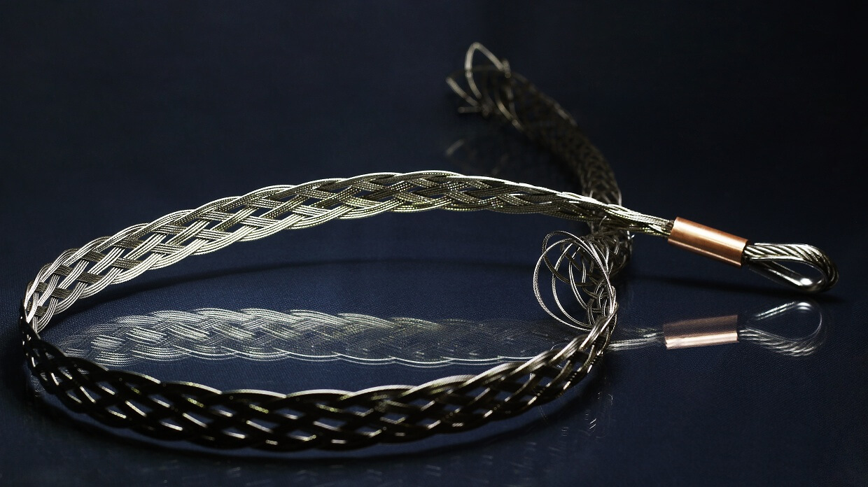
Throughout the world, it is a tried and tested practice, that cable support grips are used for the suspension of most of the cables from the nacelle in Wind Turbines. These power and control cables are usually subjected to very high stresses inside the Wind Turbines. Cable support grips provide an efficient and reliable method for supporting such cables falling from a height. These support cable grips ensure safety and durability even over a longer time span.
The support cable grips for wind turbines are specifically designed with an offset eye construction to allow smooth passage of the cables. Multiple cable grips can be applied on a single cable as well as a bundle of cables to facilitate measured support. These specialized cable support grips provide effective support and immense control over the cables installed in the Wind Turbines. Rounded copper ferrules are used to boost performance. The design also helps in minimizing the contact of the cable with the high-vibration environment. Sometimes a thimble is installed near the eyes of the grips to provide extra durability.
| CABLE SUPPORT GRIPS | ||||||
|---|---|---|---|---|---|---|
| OFFSET EYE FLEXI/THIMBLE/ CUSTOMISED CABLE GRIPS - FOR WIND TURBINES | ||||||
| Part No | Cable diameter | Safe Working Load (SF:3) | Mesh length | Total length | ||
| inches | lbs | inches | in inches | |||
| HM 10 | 0.31 – 0.39 | 550 | 19.685 | 25.591 | ||
| HM 15 | 0.39 – 0.59 | 695 | 19.685 | 26.378 | ||
| HM 20 | 0.59 – 0.79 | 695 | 19.685 | 28.346 | ||
| HM 25 | 0.79 – 0.98 | 1260 | 19.685 | 29.528 | ||
| HM 30 | 0.98 – 1.18 | 1260 | 19.685 | 29.528 | ||
| HM 40 | 1.18 – 1.57 | 1475 | 19.685 | 31.496 | ||
| HM 50 | 1.57 – 1.97 | 2475 | 31.496 | 39.37 | ||
| HM 60 | 1.97 – 2.36 | 2790 | 31.496 | 39.37 | ||
| HM 70 | 2.36 – 2.76 | 5420 | 31.496 | 47.244 | ||
| HM 90 | 2.76 – 3.54 | 6010 | 31.496 | 47.244 | ||
| HM 110 | 3.54 – 4.33 | 6550 | 31.496 | 47.244 | ||
| CABLE SUPPORT GRIPS | ||||||
|---|---|---|---|---|---|---|
| OFFSET EYE FLEXI/THIMBLE/ CUSTOMISED CABLE GRIPS - FOR WIND TURBINES | ||||||
| Part No | Cable Diameter | Safe Working Load (SF:3) | Mesh length | Total length | ||
| mm | Kg | mm | in mm | |||
| HM 10 | 08 – 10 | 250 | 500 | 650 | ||
| HM 15 | 10 – 15 | 315 | 500 | 670 | ||
| HM 20 | 15 – 20 | 315 | 500 | 720 | ||
| HM 25 | 20 – 25 | 570 | 500 | 750 | ||
| HM 30 | 25 – 30 | 570 | 500 | 750 | ||
| HM 40 | 30 – 40 | 670 | 500 | 800 | ||
| HM 50 | 40 – 50 | 1120 | 800 | 1000 | ||
| HM 60 | 50 – 60 | 1265 | 800 | 1000 | ||
| HM 70 | 60 – 70 | 2458 | 800 | 1200 | ||
| HM 90 | 70 – 90 | 2725 | 800 | 1200 | ||
| HM 110 | 90 – 110 | 2970 | 800 | 1200 | ||
For further details click here to download our Brochure or Contact us.